Tech Tip 2013-004
ATA: 62
Aircraft Model: AS350/355/EC130
Subject: Main Rotor Pitch Change Link Orientation
Date: July 25, 2013
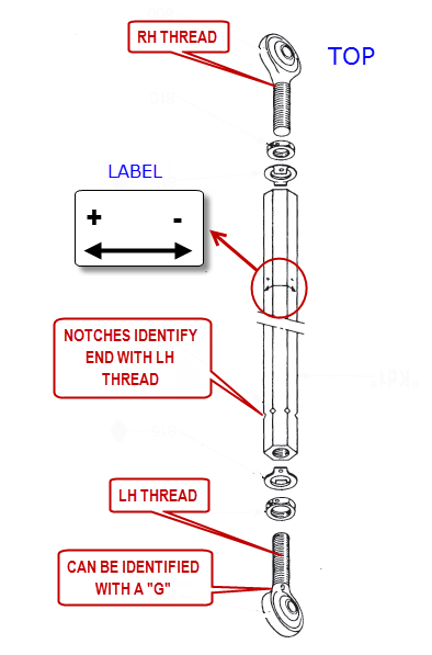
 The AS350/355 & EC130 maintenance documentation (AMM) has a statement missing regarding the correct orientation of MR pitch change links installation. Each pitch change link has a LH & a RH threaded rod end – this is to allow for length adjustment while assembly is installed. The orientation of the pitch links with correct rod ends in upper and lower position combined with the correct installation of the label is important when making tracking adjustments.
When installing the pitch change links it is not clearly defined in the maintenance documentation on how to orient the assembly. The pitch link body has notches at one end to identify the LH threaded end and the LH thread rod end can be identified with a letter “G”. The component overhaul manual specifies that the LH threaded end is to be located at the lower end. This orients the pitch link correctly for making tracking adjustments in accordance with the balancing charts.
Problems can arise when the labels are replaced and are not installed correctly. The arrow on the label is to be oriented to the LH threaded end of the pitch change link. If the label is installed in reverse the indicated adjustments will give length changes opposite to that intended.
Tech Tip 2013-005
ATA: 20
Aircraft Model: AS350 / EC130
Subject: Tools and Methods Associated with EN4165 Connectors
Date: August 26, 2013
On the newer aircraft that are being built there is a new style connector that has been integrated into production. These modular style connectors would be known to the industry as the EN4165 style connectors. You may find yourself having to work with one of these in the future and find yourself asking many questions. Fortunately, there is a guide in the Standard Practices Manual (MTC) chapter 20-80-20-421 of the AS350 / EC130 Splitvision documentation. This section documents the procedure and tools to be used for assembling these connectors and will hopefully aid in answering questions that you have as you work with them.


